Patching in Fahrenheit
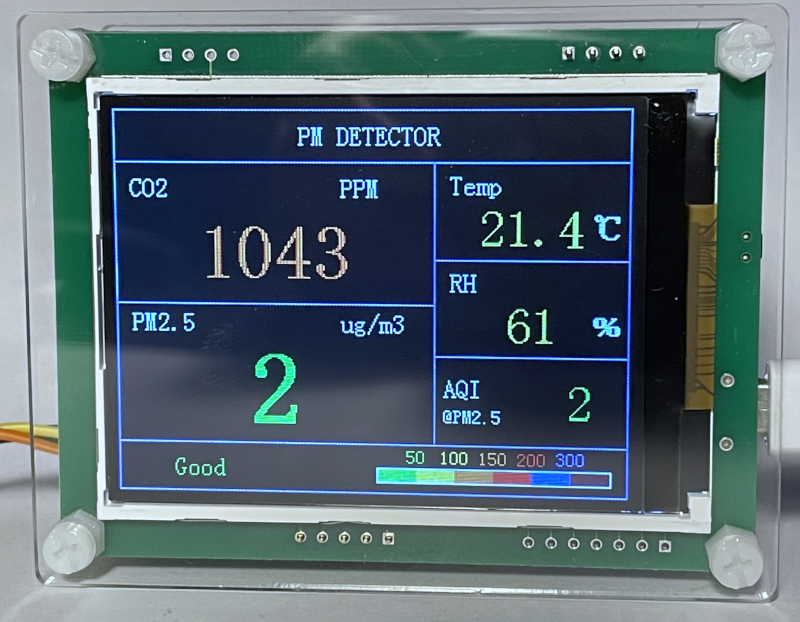
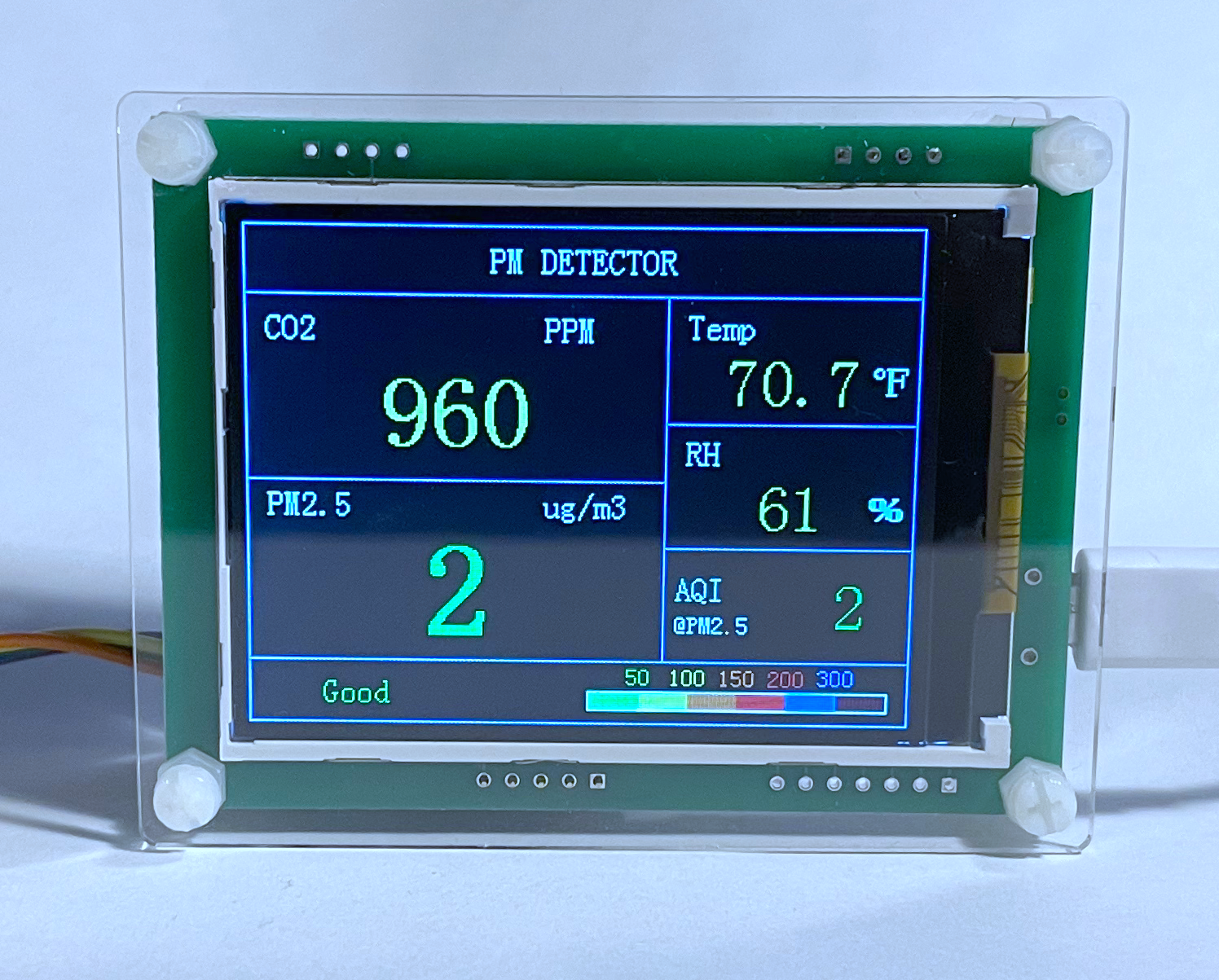
An interesting no-brand air quality monitor showed up in an Amazon search recently. The sensor is two bare PCBs with an Asair AM2120 temperature & humidity sensor, a SenseAir S8 CO2 sensor, a Plantower PMS5003 PM2.5 sensor, and a 2.8" LED display all sandwiched between two pieces of acrylic via plastic standoffs.
| Component | Price ($) |
|---|---|
| Plantower PMS 5003 | 39.95 |
| SenseAir S8 | 44.22 |
| Asair AM2120 | 1.20 |
| Z280IT010 2.8" 240x320 Display | 6.80 |
| Estimated BOM Cost | 92.17 |
| Price on Amazon | 117.79 |
| Price on banggood | 101.99 |
The monitor is only ~$25 more than the qty 1 price of the sensors, which seems like a reasonable markup to not have to write any code. An identical monitor can also be found on banggood that is priced much closer to BOM. Since the sensors are not soldered to the PCBs, if the monitor dies they can be easily removed and moved to another project.
The main downside to the monitor only applies to Fahrenheit users - the temperature display is only in Celsius!

Let's patch this thing & prove the seller wrong!
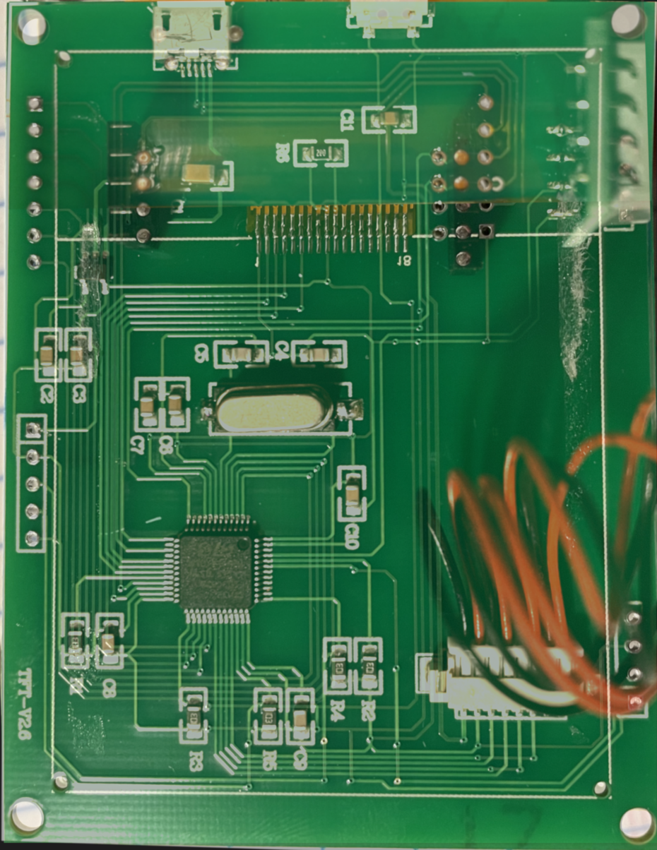
Finding the Debug Header
There are several unpopulated 0.1" headers around the PCB. From images on banggood, other variants of the monitor have additional sensors populating them. In order to dump the firmware and patch it, one of the headers needs to carry either JTAG or SWD signals.
Finding the debug header was fairly straightforward, using a very similar method to the one demonstrated by Eric Schlaepfer. The monitor was disassembled and well-lit pictures of both sides of the PCB were overlaid with reduced opacity so traces on the top and bottom layers could be seen together.
Note: Mirroring the side of the PCB containing the MCU makes it very difficult to match pins to the datasheet!
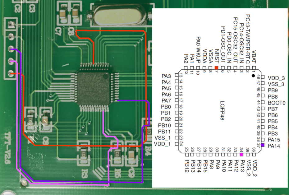
The STM32F103C8 was given away by the silkscreen and the datasheet highlighted the likely SWD pins.
| Pin Name | Main Function |
|---|---|
| PA13 | JTMS/SWDIO |
| PA14 | JTCK/SWCLK |
Fortunately, PA13 & PA14 traced out to the same header with NRST - the SWD debug header was found! The remaining two pins in the header were continuity checked against the 3.3V and GND from the AM2120 to determine polarity.
Dumping the Firmware
With the debug header discovered and mapped, it is straightforward to wire up a JTAG programmer (STLink, J-Link EDU, etc).
| Pin Name | SWD Connector Pin | PCB Header Pin |
|---|---|---|
| VTref | 1 | 1 |
| GND | 4 | 2 |
| SWCLK | 9 | 3 |
| SWDIO | 7 | 4 |
| RESET | 15 | 5 |
Dumping the firmware can be accomplished with openocd, a sample config file for this target with a J-Link is:
source [find interface/jlink.cfg]

transport select swd

source [find target/stm32f1x.cfg]openocd.cfgFortunately, the flash is not read-protected and can be extracted with flash read_bank 0 bank0.bin 0x0 0x1FFF via the telnet interface to openocd.
$ openocd -f openocd.cfg
Open On-Chip Debugger 0.10.0
Licensed under GNU GPL v2
For bug reports, read
	http://openocd.org/doc/doxygen/bugs.html
adapter speed: 1000 kHz
adapter_nsrst_delay: 100
none separate
cortex_m reset_config sysresetreq
Info : No device selected, using first device.
Info : J-Link V10 compiled Mar  7 2019 15:19:19
Info : Hardware version: 10.10
Info : VTarget = 3.328 V
Info : clock speed 1000 kHz
Info : SWD DPIDR 0x1ba01477
Info : stm32f1x.cpu: hardware has 6 breakpoints, 4 watchpoints
$ telnet 0 4444
Trying 0.0.0.0...
Connected to 0.
Escape character is '^]'.
Open On-Chip Debugger
> flash list
{name stm32f1x base 134217728 size 0 bus_width 0 chip_width 0}
> flash read_bank 0 bank0.bin 0x0 0x1FFFF
device id = 0x20036410
flash size = 64kbytes
wrote 131071 bytes to file bank0.bin from flash bank 0 at offset 0x00000000 in 1.897898s (67.443 KiB/s)
Finding the Temperature Drawing Function
With the firmware stored in bank0.bin it's time to fire up ghidra and determine where the temperature is being displayed.
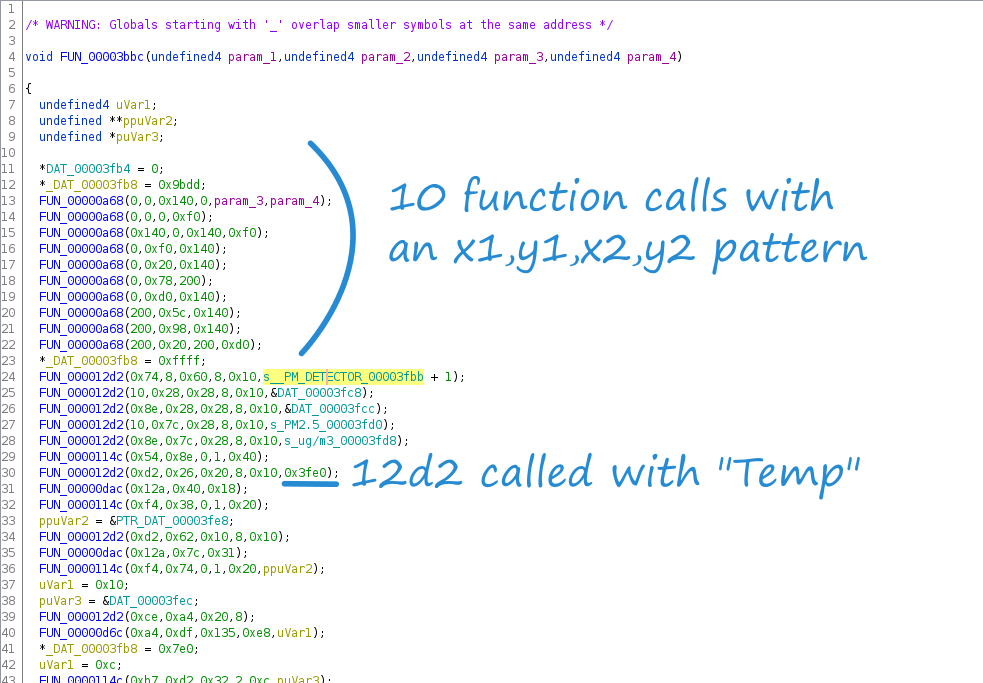
PM DETECTOR appears on the monitor's display which makes it a good candidate to find the screen drawing function(s). Fortunately, PM DETECTOR appears as a "Defined String" in the binary. The function defined at 00003bbc uses the string.
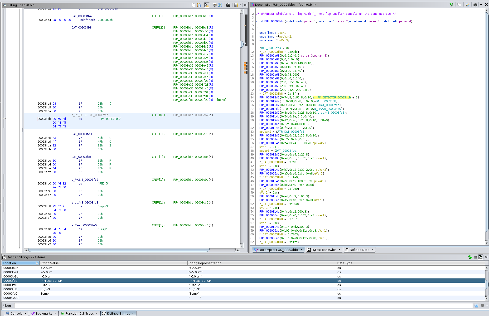
Taking a deeper look at this function reveals that there are 10 calls to a function with 4 arguments; coincidentally there are 10 lines on the display. The arguments to this function also appear to be in an x1,y1,x2,y2 format. Additionally, _DAT_0003fb8 is set to 0x9bdd - a shade of blue in the RGB565 space. So, it seems that FUN_00003bbc is responsible for drawing the main screen of the monitor.
FUN_000012d2 appears to be drawing strings to the screen, and the call on L30 has the address for the "Temp" string. Ghidra does not detect strings less than 5 characters, so "Temp" was not formatted in a similar fashion to "PM DETECTOR".
FUN_00003bbc Static Screen 1 Draw FunctionThe "Function Call Tree" feature of ghidra highlights which functions call a particular function. Renaming FUN_00003bbcto Screen1Static() makes it clearer what is going on in the parent function, FUN_000047a6.
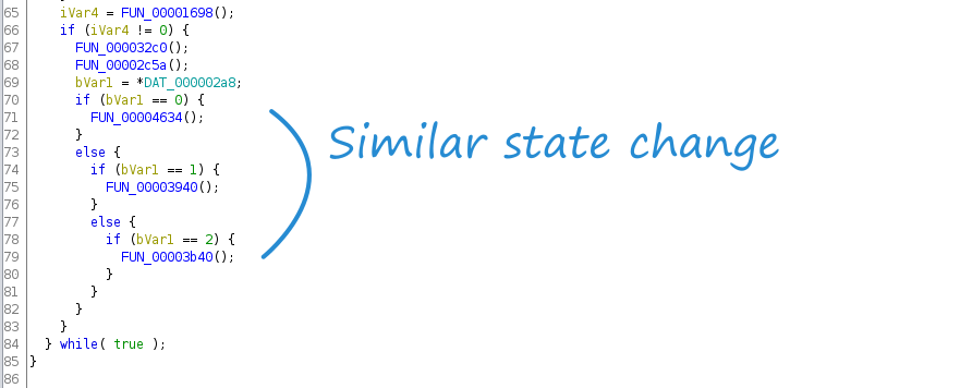
FUN_000047a6 calls Screen1Static() once before a infinite loop, and then again in the infinite loop which has different behavior depending on the value of iVar4. Taking a look inside of FUN_00003142, it is clear it is returning the state of a digital input; when the side button of the monitor is pressed, the display will cycle through three screens, suggesting iVar4 maps to the side button and bVar1/ pbVar2 maps to the number of times the button has been pressed.

A similar state change based on iVar4 /bVar1 occurs later on in FUN_000047a6 (presumably the "main" function), suggesting that FUN_00004634 may be the function performing the dynamic update of the sensor readings.
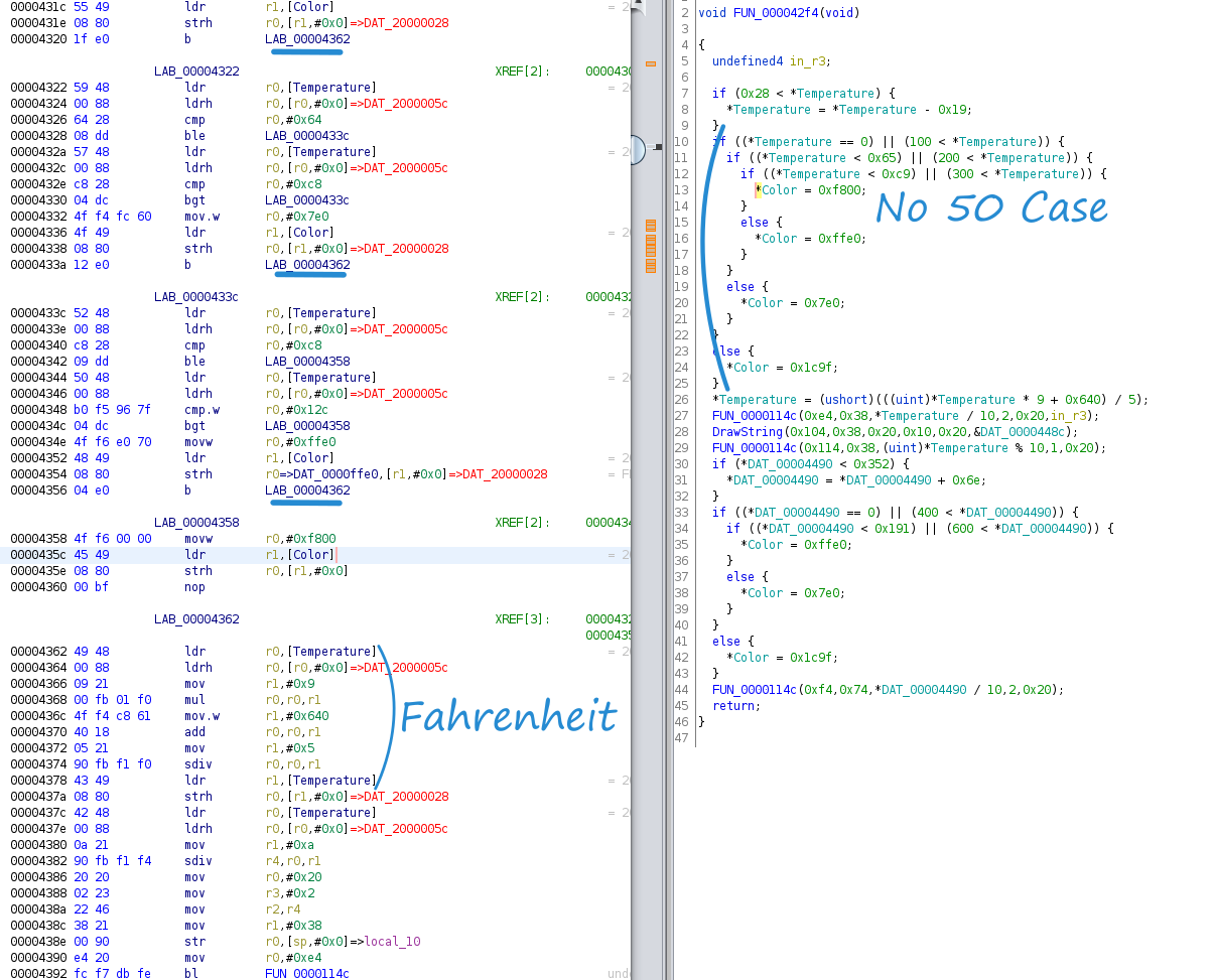
FUN_00004634 is a wrapper function that only calls four other functions, the second being FUN_000042f4. FUN_000042f4 contains two function calls which divide an argument by 10; the AM2120 datasheet specifies that humidity and temperature readings are 10 times larger than the actual value. It looks very promising that this is the function displaying the temperature and humidity to the screen.
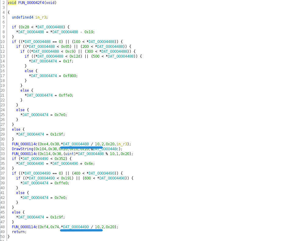
Furthermore, L31 - L33 print a number divided by 10, a decimal point, and then the modulus of the number with respect to 10. In other words, these three lines print "716" as "71.6". The only value printed to the monitor's screen which has a decimal is the temperature reading - the temperature drawing function has been found!
Patching in Fahrenheit
Because the temperature value returned by the AM2120 is 10x the actual temperature in Celsius, the usual Fahrenheit to Celsius formula needs adjusted:
$$F = \frac{9}{5}C + 32$$
$$F^* = 10F$$
$$C^* = 10C$$
$$\frac{F^* }{10} = \frac{9 C^* }{50} + 32$$
$$F^* = \frac{9 C^* }{5} + 320 = \frac{9 C^* + 1600}{5}$$
Transcribing the formula to ARM assembly is fairly straightforward. Unfortunately, many ARM assembly simulators do not support sdiv so the first time the code was tested was live on the processor!
ldr        r0,[Temperature]		# Load the temperature address
ldrh       r0,[r0,#0x0]			# Load the temperature value
mov        r1,#0x9			# Move 9 into r1
mul        r0,r0,r1			# Multiply temperature by 9
mov.w      r1,#0x640			# Move 1600 to r1
add        r0,r0,r1			# Add 9*C to 1600
mov        r1,#0x5			# Move 5 to r1
sdiv       r0,r0,r1			# Divide 9*C+1600 by 5
ldr        r1,[Temperature]		# Load temperature address
strh r0,[r1,#0x0] # Store the temperatureWith the assembly in hand, the next step was to find an appropriate place to insert the ten instructions. Right above the call to FUN_0000114C (draw a number to the screen) the color for the number draw is selected.
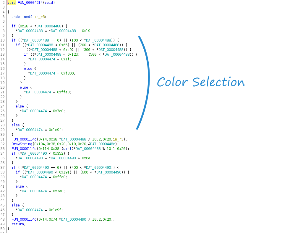
The color (DAT_00004474) is based on the value of the temperature reading (10x the temperature in ℃). The color scheme is RGB565 which fits in 2 bytes instead of the three bytes required for RGB888. The values can be trivially converted to RGB888 color space using the snippet of Python below.
def rgb565_to_rgb888(rgb565):
    red = (rgb565 & 0xf800) >> 8
    green = (rgb565 & 0x7e0) >> 3
    blue = (rgb565 & 0x1f) << 3
    return red, green, blue

rgb565_to_rgb888(0x1c9f)
(24, 144, 248)| RGB565 | RGB888 | Color | Temperature Range |
|---|---|---|---|
| 0x1f | (0, 0, 248) | Blue | > 50℃ |
| 0xf800 | (248, 0, 0) | Red | 30℃ - 50℃ |
| 0xffe0 | (248, 252, 0) | Yellow | 20℃ - 30℃ |
| 0x7e0 | (0, 252, 0) | Green | 10℃ - 20℃ |
| 0x1c9f | (24, 144, 248) | Light Blue | < 10℃ |
Displaying a different color for values above 50℃ does not necessarily provide a lot of value, so that functionality is a prime candidate for replacing with the Fahrenheit conversion function.
The block of assembly at 00004376 sets the Color to 0x1f (Blue) and all of the jumps to that label occur in the block 00004358, right above it, so it looks like overriding this functionality will work cleanly.
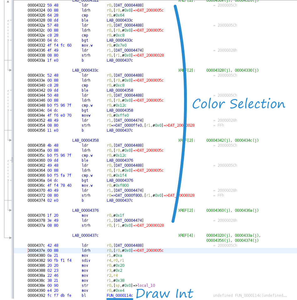
Starting at 0000437a and working up, the 10 Fahrenheit instructions fit in neatly with one dangling instruction at 00004360 which can be converted to either a nop or a direct jump to 00004362. Since all branches of the color selection tree should calculate Fahrenheit, all of the jumps to 0000437c (the ℃ read) need updated to 00004362 (the ℉ read). Note that at first blush it looks like the instructions at 00004378:437a are redundant since the Temperature value is stored and then immediately read. Storing the Temperature is necessary for the tenth of a degree draw call after the decimal point is drawn.
In theory, the temperature reading should be converted to Fahrenheit and printed to the screen!
Fixing the ℃ Glyph
Calculating the temperature in Fahrenheit is only half the battle - the display has a ℃ glyph which needs to be updated to ℉. In the screen setup function there are two similar calls right after the "Temp" and "RH" (Relative Humidity) strings are drawn to the screen. Both the "Temp" and "RH" cells in the also have static units drawn in them,℃ and %, respectively.
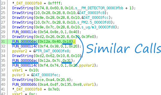
Diving into the suspicious function, it appears to have three nested loops, the outer running 16 times, the middle running 8 times, and the inner running 2 times for a total of 256 (or 16x16) iterations. The ℃ and the % glyphs on the display both look like 16x16 bitmaps, further suggesting that this function is indeed blitting a 16x16 image to the display. Both the ℃ and % appear to be in the same x column on the display, suggesting that the first argument to FUN_00000dac is the x-coordinate, the second argument being the y-coordinate, with the third paramter potentially being an index into a sprite array.
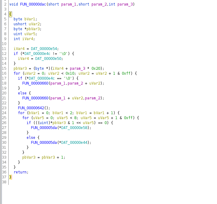
Assuming that third parameter is indeed a sprite index, it is possible to calculate the memory address for each glyph by multiplying the index by 256 and adding that to the address located at DAT_000000e50 (Line 15 in the disassembly). However, for reasons that will become apparent, this binary data did not seem to match the expected pattern for the ℃ glyph.
Fortunately, with a bit of imagemagick black magic we can visually hunt for these glyphs! The following snippet reads in the binary file as a 16x16384 image (one long column), breaks that column into 16x16 sections, and then stitches them back together, effectively y-axis overflow wrapping the 16x16384 column.
montage <(convert -depth 1 -size 16x16384 gray:bank0.bin -crop 16x16 miff:-) -tile 1x32 -geometry 16x16+0+0 miff:- | montage - -geometry +0+0 -tile x1 binary.png
With a little bit of searching it's possible to find the ℃ which just so happens to be at the exact memory location it was supposed to be ( 0x47c6 + 0x18*256)! However, the image is rotated and has an 8 bit offset.

With the format known, it was trivial to create a similar ℉ glyph and patch the binary with the hex representation.

Flashing the modified firmware
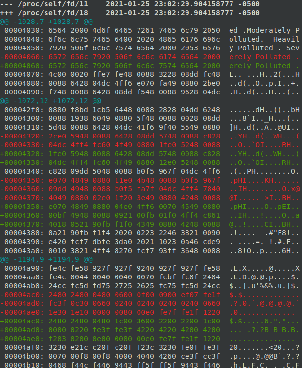
Diffing the two firmware images shows the three distinct regions that were patched; a fixed typo at 00004060, the Fahrenheit formula at 00004320, and the °F glyph update at 00004ac0:
diff -u <(xxd bank0.bin) <(xxd bank0.bin.mod)
Reflashing the modified binary to the monitor is straightforward using openocd:
halt
stm32f1x unlock 0
reset halt
stm32f1x mass_erase 0
flash write_bank 0 bank0.bin.mod 0x0
And now the temperature displays in Fahrenheit with a proper unit designation!
Edit: Many thanks to dmitrygr for playing code golf on the core of the asm function!
movw r1, #0xe677
muls r1, r0
lsrs r1, #15
add r1, #320
Did this inspire you to go out and hack something? Say thanks and help keep this site ad & analytic free by using my Amazon Affilliate URL. I'll receive a small portion of any purchases made within 24 hours.