Solving the Nintendo Switch Ground Loop
Solving ground loop issues when connecting the Nintendo Switch to a computer and analyzing some ground loop isolators along the way

Some Nintendo Switch games have stronger game play mechanics than soundtracks and it would be nice to listen to other music will still being able to hear critical sound effects. Having an ear bud playing sounds from the Nintendo Switch inside of an over-ear headphone playing music does work, but can be painful after a few hours. In theory, it should be possible to run the Nintendo Switch's audio through a computer and into a single set of headphones.
First Attempt
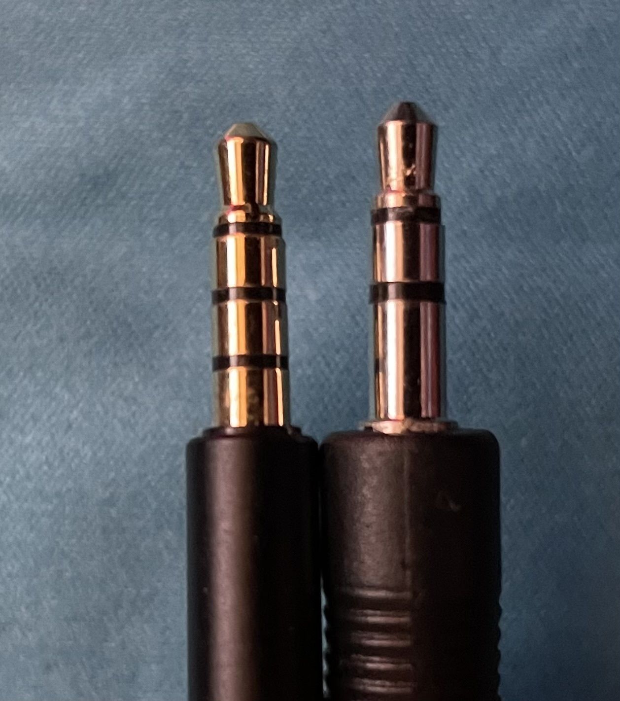
The Nintendo Switch has a TRRS (Tip-Ring-Ring-Sheath) 3.5mm port which carries the left and right audio channels, a ground line, and the microphone channel. Most 3.5mm devices use a TRS (Tip-Ring-Sheath) connector which only carries left/right and ground. TRRS and TRS ports and cables can be used interchangeably for carrying left and right audio channels, but a TRRS cable must be used in a TRRS port to carry the microphone signal.
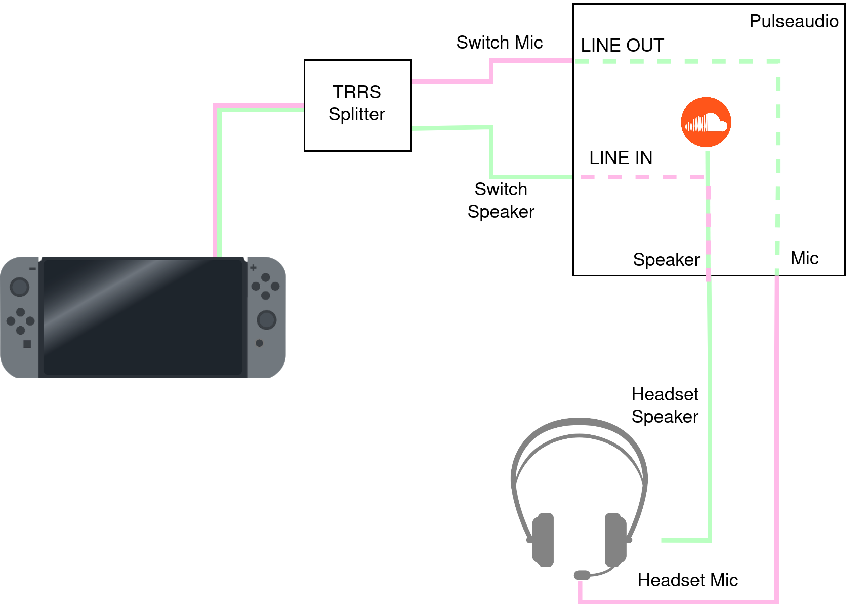
In theory, it should be possible to take the left and right audio channels from the Nintendo Switch and pipe those to a LINE IN line on a computer. The LINE IN could then be mirrored onto a headphone jack that is already playing some other music. Similarly, piping a microphone from the computer to the LINE OUT and wiring that to the Nintendo Switch microphone input should also preserve microphone functionality. A TRRS to 2xTRS splitter can be used to pipe the left and right audio channels to the LINE IN port and the microphone to the LINE OUT port on the motherboard.
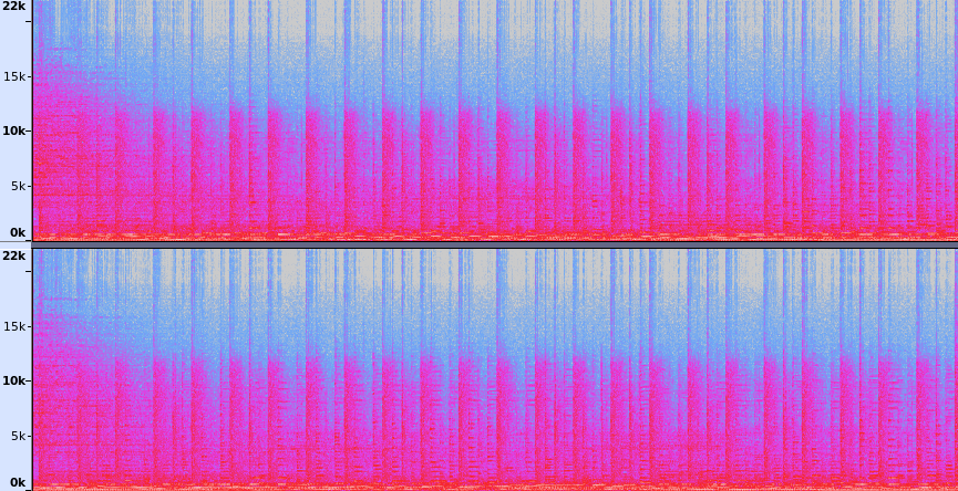
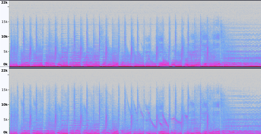
However, doing this in practice results in some nasty noise from a ground loop. The spectrogram below shows the unpleasant broadband noise that drowns out the real audio signal.
Ground Loop Isolators
Ground loop isolators are commonly used to remove noise from improperly installed 3rd party car stereos and can easily be found online. Most isolators work by using transformers to transfer the audio signal with a new ground. However, it is not always apparent from the product listing how the isolator actually performs. Since two isolators are needed (one for the mic, one for the stereo) three were purchased and characterized side-by-side.
- PAC SNI-1/3.5 Ground Loop Isolator. The ground loop isolator of choice at Crutchfield and claims to have a +1.3dB response.
- Zetsage Ground Loop Noise Isolator. This product was the cheapest of a slew of seemingly identical MPOW clones on Amazon. The product images suggest that the isolator is not using transformers for isolation.
- Kript Hifi Ground Loop Isolator. The Kript product images showed real isolation transformers.
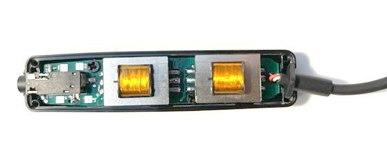
The Kript HiFi was the only isolator that was trivial to crack open and is shown above. The PAC has end caps clipped into the PCB but it possible to remove grommets holding the 3.5mm wire and verify that there are transformer coils inside. The Zetsage seems glued together and did not want to reveal its secrets.
The three isolators were characterized using a Digilent Analog Discovery 2 as a vector network analyzer with a 2V signal swept from 20Hz-20,000Hz (audible range). Digilent's Waveforms software shows the full bode plot of the response, as shown in the run against the Zetsage, below. The generated waveform is Channel 1 (yellow trace) and the response through the ground loop isolator is Channel 2 (blue trace).
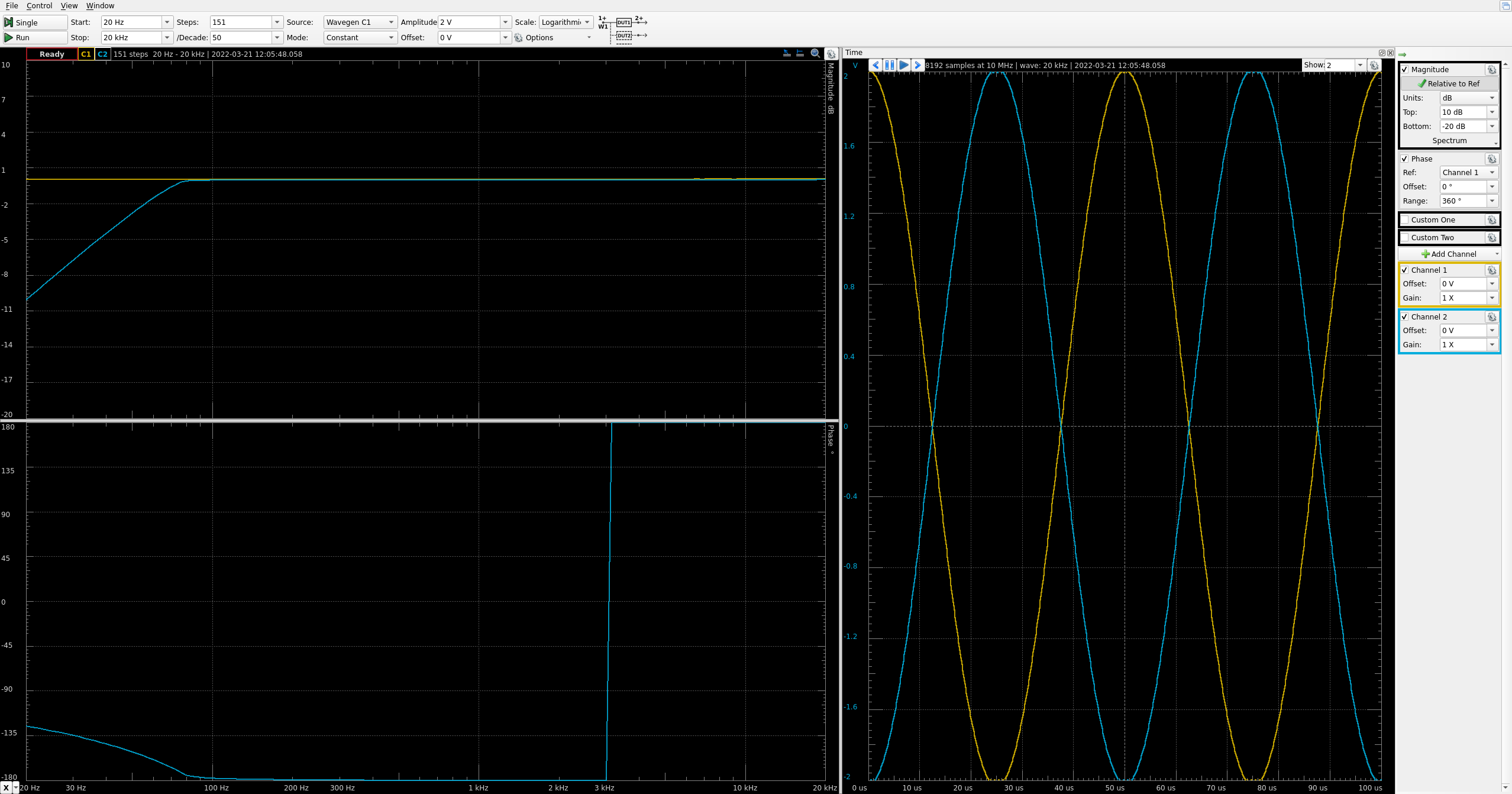
Interestingly, the Zetsage was the only device to reproduce the waveform with a 180° phase offset which inverted at 3kHz! Both the PAC and Kript devices reproduced the waveform with 0° offset after ~100Hz.
The amplitude response of the three devices is shown below.
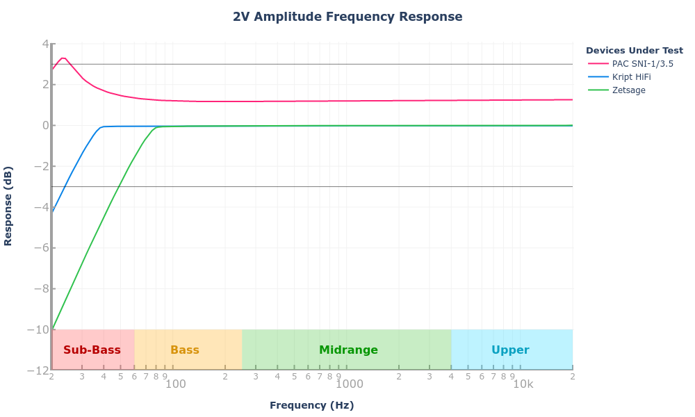
The PAC SNI-1/3.5 lived up to the advertised +1.3dB gain (+16%) across the majority of the frequency range. Running the device in reverse inverts the gain to -1.3dB.
The Kript and Zetsage both target a 0dB gain with -0.08dB being achieved by the Kript at 39Hz and 80Hz for the Zetsage. Multiple Amazon reviews for the Zetsage (and other no-name ground loop isolators) complained about weaker bass which aligns with the frequency response results.
Putting the Kript and the PAC ground loop isolators in line with the audio signals from the Switch results in a much cleaner spectrogram without broadband noise.
Pulseaudio
With the ground loop resolved it is finally possible to set up the loopback devices allowing the Nintendo Switch speaker output and microphone input to be proxied to other devices.
The first step is to use pactl to determine which source ("input" in pulseaudio parlance) is wired to the Nintendo Switch left/right audio channels.
$ pactl list sources | grep -e Source -e Name -e Port
Source #14
	Name: alsa_output.pci-0000_0e_00.3.HiFi__hw_Generic_4__sink.monitor
Source #15
	Name: alsa_output.pci-0000_0e_00.3.HiFi__hw_Generic__sink.monitor
Source #16
	Name: alsa_input.pci-0000_0e_00.3.HiFi__hw_Generic_4__source
	Ports:
	Active Port: [In] Mic1
Source #17
	Name: alsa_input.pci-0000_0e_00.3.HiFi__hw_Generic__source
	Ports:
	Active Port: [In] Mic2
In this case the microphone port being used is the shared Rear Mic/Line In port which is Source #17. Source #16 is also a microphone line but is the microphone that will be piped to the Switch.
pactl can also be used to find the sink ("output") to redirect the input to. In this setup the proper sink are the headphones at index #8. Note: Bluetooth headsets in an A2DP configuration will have noticeable lag in online games.
pactl list sinks | grep -e Sink -e Name -e Port
Sink #8
	Name: alsa_output.pci-0000_0e_00.3.HiFi__hw_Generic_4__sink
	Ports:
	Active Port: [Out] Headphones
Sink #9
	Name: alsa_output.pci-0000_0e_00.3.HiFi__hw_Generic__sink
	Ports:
	Active Port: [Out] Line1
With the sink and source numbers known the loopback module can be loaded. The latency_msec parameter is a target for latency and defaults to 200ms to preserve CPU cycles. In the case of gaming, 200ms is too high and should be lowered in exchange for higher CPU load on the host PC.
pactl load-module module-loopback sink=8 source=17 latency_msec=5
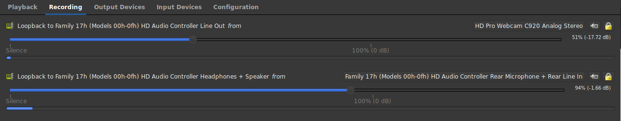
With the loopback module loaded audio from the Nintendo Switch is played over the headphones! The loopback connection shows up in the "Recording" tab of pavucontrol. Note that it is possible to change the sink target from pavucontrol but not the source.
The exact same procedure is used to pipe a microphone to LINE OUT which is wired to the microphone input of the Nintendo Switch:
pactl load-module module-loopback sink=9 source=16
The modules can be loaded at boot by adding equivalent lines to ~/.config/pulse/default.pa. The sink and source numbers can change every time pulseaudio is launched, so it can be convenient to swap the index numbers out for the actual device names.
...
load-module module-loopback sink=alsa_output.pci-0000_0e_00.3.HiFi__hw_Generic_4__sink source=alsa_input.pci-0000_0e_00.3.HiFi__hw_Generic__source latency_msec=5

load-module module-loopback sink=alsa_output.pci-0000_0e_00.3.HiFi__hw_Generic__sink source=alsa_input.pci-0000_0e_00.3.HiFi__hw_Generic_4__source
...
Microphone Circuit
While the pulseaudio switcheroo above is sufficient to listen to audio from the Nintendo Switch, it is not sufficient to pipe the external microphone into games.
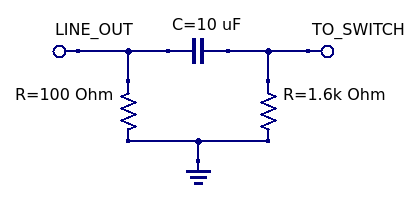
Nearly all devices using TRRS connectors for microphone input put a bias voltage on the line to power the microphone. The fluctuations in voltage caused by the microphone are then treated as an audio input. Most devices detect the presence of a microphone as the lack of a short between the Sleeve and Ring; the ground isolation transformer is essentially a short in this case. To remedy this, a resistor needs placed between the microphone input and ground. Google recommends 1k Ohm or higher for microphones connecting to an Android device. A 1.6k Ohm resistor was readily available and works just fine.
The DC bias voltage is problematic - it is not needed since the audio signal is coming from the Line Out of the computer. To prevent the DC bias voltage from interferring with the ground loop isolator, a capacitor can be used in series with the signal.
Additionally, "mic level" is generally recognized as -40 dB while consumer grade line levesl are generally -10 dB. A voltage divider could be built in hardware to reduce the voltage levels, but pavucontrol provides a handy limiter for the output strength of the Line Out signal.
TRRS to Screw Terminal breakouts make it easy to build the circuit below.
Bill Of Materials
The total cost to re-implement seems a bit higher than it should! This cost could probably be reduced from hacking together homemade isolation transformers or salvaging TRRS cables.
| Component | Price |
|---|---|
| 3.5mm TRRS Male-to-Male Cable | $8.79 |
| 3.5mm TRRS to 2x TRS Adapter | $5.99 |
| Kript Hifi Ground Loop Isolator | $14.99 |
| PAC SNI-1/3.5 Ground Loop Isolator | $9.94 |
| TRRS Breakout Adaptors | $12.62 |
| Total | $52.33 |
Was this an interesting read? Say thanks and help keep this site ad & analytic free by using my Amazon Affilliate URL. I'll receive a small portion of any purchases made within 24 hours.